SparkCore with .Net – Part 2.

Introduction

This article picks up from where we left off in part 1. I would suggest reading it first.  You can find the download links there an a good introduction to our hardware setup.

We are going to now replace the Tinker API code that loads natively on the SparkCore with our own code.  The goal here is to move the complexity from the client to the service provider (aka The Robot).  By placing the bulk of the code on the SparkCore we will eliminate the need to asynchronously call the commands we use the set the motors turning.  We are also positioning ourselves for future enhancements which can be handled better local to the robot (ie. Distance sensors to prevent the robot from running into a wall).  Additionally, we will be moving from the TinkerAPI class to the CoreAPI class.

SparkIODotNet CoreAPI Class

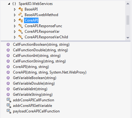
The CoreAPI class gives .Net developers access to the core Spark.function() and Spark.variable() features of the SparkCore’s firmware.   These methods register functions and variables to be accessible as REST calls on the SparkCloud.  Below is the Class View of the CoreAPI which I will explain.

CoreAPI

The CoreAPI class has the same constructors as the TinkerAPI class.  The methods are split into two groups – one for calling Spark.function() and one for calling Spark.variable().  The CallFunction* methods are broken up by the expected return values (boolean, double, int and stirng).  Under the hood, the data coming from the SparkCloud is text in the JSON REST response.  S0, when we’ve retrieved the value it is text.  The base method is CallFunctionString and all of the other methods are TryParses of it.  Similarly, the GetVariable* works the same way to retrive the exposed variables from the SparkCore’s program.

New Program for the Robot

When I went to start writing the custom code for the SparkCore to drive the robot around, I found a sample already loaded in the editor by the folks at Spark.  I made a few small modifications to allow the robot to travel in left and right arcs while moving forward or backward.  The code is shown below and should be very familiar to anybody who has worked in C on the Arduino platform.

/* A Spark function to parse the commands */
int rcCarControl(String command);

/* Globals -------------------------------------------------------------------*/
int leftMotorSpeed   = A1;
int rightMotorSpeed  = A0;
int leftMotorDir     = D3;
int rightMotorDir    = D2;

int speedStop  = 0;
int speedHalf  = 25;
int speedFull  = 250;

/* This function is called once at start up ----------------------------------*/
void setup()
{
  //Register Spark function
  Spark.function("rccar", rcCarControl);

  //Register Spark variable
  Spark.variable("speedStop", &speedStop, INT);
  Spark.variable("speedHalf", &speedHalf, INT);
  Spark.variable("speedFull", &speedFull, INT);

  pinMode(leftMotorDir, OUTPUT);
  pinMode(leftMotorSpeed, OUTPUT);
  pinMode(rightMotorDir, OUTPUT);
  pinMode(rightMotorSpeed, OUTPUT);

  pinMode(D7,OUTPUT);

}

/*uint16_t This function loops forever --------------------------------------------*/
void loop()
{
  // Nothing to do here
}

/*******************************************************************************
 * Function Name  : rcCarControl
 * Description    : Parses the incoming API commands and sets the motor control
                    pins accordingly
 * Input          : RC Car commands
                    e.g.: rc,FORWARD
                          rc,BACK
 * Output         : Motor signals
 * Return         : 1 on success and -1 on fail
 *******************************************************************************/
int rcCarControl(String command)
{
  if(command.substring(3,7) == "STOP")
  {
    analogWrite(leftMotorSpeed, speedStop);
    analogWrite(rightMotorSpeed,speedStop);

    digitalWrite(leftMotorDir, LOW);
    digitalWrite(rightMotorDir,LOW);

    return 1;
  }

  if(command.substring(3,11) == "BACKLEFT")
  {
    digitalWrite(leftMotorDir, LOW);
    digitalWrite(rightMotorDir,LOW);

    analogWrite(leftMotorSpeed, speedHalf);
    analogWrite(rightMotorSpeed,speedFull);

    return 1;
  }

  if(command.substring(3,12) == "BACKRIGHT")
  {
    digitalWrite(leftMotorDir, LOW);
    digitalWrite(rightMotorDir,LOW);

    analogWrite(leftMotorSpeed, speedFull);
    analogWrite(rightMotorSpeed,speedHalf);

    return 1;
  }

  if(command.substring(3,7) == "BACK")
  {
    digitalWrite(leftMotorDir, LOW);
    digitalWrite(rightMotorDir,LOW);

    analogWrite(leftMotorSpeed, speedFull);
    analogWrite(rightMotorSpeed,speedFull);

    return 1;
  }

  if(command.substring(3,14) == "FORWARDLEFT")
  {
    digitalWrite(leftMotorDir, HIGH);
    digitalWrite(rightMotorDir,HIGH);

    analogWrite(leftMotorSpeed, speedHalf);
    analogWrite(rightMotorSpeed,speedFull);

    return 1;
  }

  if(command.substring(3,15) == "FORWARDRIGHT")
  {
    digitalWrite(leftMotorDir, HIGH);
    digitalWrite(rightMotorDir,HIGH);

    analogWrite(leftMotorSpeed, speedFull);
    analogWrite(rightMotorSpeed,speedHalf);

    return 1;
  }

  if(command.substring(3,10) == "FORWARD")
  {
    digitalWrite(leftMotorDir, HIGH);
    digitalWrite(rightMotorDir,HIGH);

    analogWrite(leftMotorSpeed, speedFull);
    analogWrite(rightMotorSpeed,speedFull);

    return 1;
  }

  if(command.substring(3,8) == "RIGHT")
  {
    digitalWrite(leftMotorDir, HIGH);
    digitalWrite(rightMotorDir,LOW);

    analogWrite(leftMotorSpeed, speedFull);
    analogWrite(rightMotorSpeed,speedFull);

    return 1;
  }

  if(command.substring(3,7) == "LEFT")
  {
    digitalWrite(leftMotorDir, LOW);
    digitalWrite(rightMotorDir,HIGH);

    analogWrite(leftMotorSpeed, speedFull);
    analogWrite(rightMotorSpeed,speedFull);

    return 1;
  }

  // If none of the commands were executed, return false
  return -1;
}

The work horse function, rcCarControl, is at line 50. This function takes a string that chooses the pin configuration to accomplish the desired robot operation.  This is just a normal C function unless you look at line 18.  This line uses the Spark.function() to register rcCarControl as a REST call in the SparkCloud with the name rccar.  If you looked at the Helper class in the DrivEmTinkerAPI, you’ll notice the C code looks familiar.  All of the complexity has moved to the SparkCore program and exposes the functionality as a single simple service.  The DrivEmCoreAPI WinForm’s Helper class is now considerably simpler.

Let’s take a look at what is required now to make our robot move forward.  In the WinForm, when you press the Forward button, the MouseDown event will fire and call the GiveCommand method of the Helper class.  The GiveCommand method is now one-line.

public void GiveCommand(DriveCommands command)
{
    int iresult = core.CallFunctionInt("rccar", "rc," + command.ToString());
}

The DriveCommands enum in the helper class has its names directly mapped to the strings expected by the SparkCore’s rcCarControl() function. We prepend an ‘rc’ to the command and send it to the SparkCore.  We are using the CallFunctionInt function to call the rccar Spark.Function with the expectation of an integer result.  IN our example, there is no error handling present for the result and this can be added later.  In line 18 of the SparkCore DrivEm program above, we wire up the ‘rccar’ tag to the rcCarControl function.  Now when the CoreAPI’s CallFunctionInt passes ‘rccar’ and an arguement, this is how it gets routed to where it needs to go.

You will also notice something else missing… Async calls.  Since the pins are all switched by a single command from our client on the SparkCore board itself… it happens fast enough that we don’t notice the slight lurch to the left or right when we start moving forward.

So in a nutshell, the SparkIODotNet library will help you get a quick prototype up and running with the pre-loaded TinkerAPI.  When you move further into the project, you can start writing custom code for the SparkCore and move to using the CoreAPI to access your custom functions directly.  Good Luck tinkering!
SparkCore with .Net – Part 1.

Introducing the SparkCore

The SparkCore is a tiny Wi-Fi development board that makes it easy to create internet-connected hardware. It is also the first thing I’ve gotten from KickStarter.  I’ve been experimenting with my Netduino board now for a few months and I have been waiting for my SparkCore to arrive.  It is very much like the Netduino and Arduino boards with the exception of being Wi-Fi ready and primarily designed to interact with the Internet.  It has a web based programming environment that allows you to build a program and flash it to the SparkCore over the Internet.  Prior to writing some SparkCore code, I want to get familiar with the SparkCore’s TinkerAPI.

SparkCore

The TinkerAPI is the default program that comes loaded the board.  It provides basic functionality to control the analog and digital pins via REST API calls on the SparkCore cloud.  When the SparkCore turns on, it connects to the Spark Cloud via Wi-Fi.  The cloud exposes the functionality of the digital and analog pins via a collection of REST services.  When these services are called in the cloud, the SparkCore makes the requested changes to its pin’s states or returns their values.  So, to make this all usable in .Net, I have written a class library to make these services easily callable.  Additionally, the library will call the native web enabled variables and functions available when writing your own code for the SparkCore.

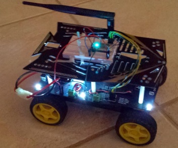
So, to make this whole exercise fun, we are not turning LEDs on and off or reading the temperature.  We will be driving a robot!  I coupled the SparkCore with a dfrobot Cherokey 4WD Mobile Robot.  Below is my the Cherokey with my SparkCore zip tied into place.  My SparkCore is the variety with the u.FL connector which allowed me to attach the external antenna which I have mounted on the chassis.

Cherokey and SparkCore

The Cherokey comes with a battery holder that takes 5 AA batteries.  This is grossly inadequate to power the board and the motors.  It was very frustrating working with the Cherokey with th eout of the box power source so I rectified the problem.  I visited the local hobby shop and purchased an Onyx 7.2V 3000 mAh NiMH battery and a pig tail.  I removed the AA battery holder zip tied the new battery under the robot’s upper deck.  I attached the pigtail to the battery posts on the main board and plugged in the battery.  I powered on the robot and gave it some commands.  The robot zipped around as fast as could be… don’t waste your time with the ‘in the box’ battery setup.

Wiring Up the SparkCore to the Cherokey

Wiring up the SparkCore to the Cherokey involves two different items – power and control signals.  The power hookup is very simple and only involves GND and 5V Power.  The below diagram shows the layout of the SparkCore’s power pins and the Analog (A0-A7) and Digital (D0-D7) pins.

The below diagram shows the layout of the Cherokey pins with an Arduino board on it.  We will be focusing on the 5V output and GND pins.  We will also focus on pins D4 – D7 which control the motors.

Cherokey Board

Wiring Up Power

The Cherokey is powered by the large 7.2V NiMH battery which shouldn’t be attached to the SparkCore directly.  The Cherokey board steps down the voltage and provides us with a couple locations to get 5V DC output and GND.  The battery is attached to the VCC and GND terminals on the right side of the Cherokey board.  Wire power as follows from the Cherokey to the SparkCore:

Cherokey SparkCore
5V VIN
 GND  GND

Wiring up Motor Control

The Cherokey’s control board takes two type of input signals form the SparkCore.  The first type is on the D4:M1_EN and D6:M2_EN pins.  These pins control the direction the Right and Left wheels will turn respectively.    These input lines are digital and are expecting HIGH for forward and LOW for reverse.  D4:M1_PWM and D7:M2_PWM control the speed of the Right and Left wheels respectively.  These input lines are looking for a PWM signal from the SparkCore.  The SparkCore can generate PWM output on the pins A0, A1, A4, A5, A6, A7, D0 and D1.  Wire control as follows from the SparkCore to the Cherokey:

SparkCore Cherokey
D0 D5
D1 D7
D2 D4
D3 D6

SparkCore’s TinkerAPI

Now that we have the SparkCore setup with its connection to the Cherokey, we are essentially done on the hardware side and only have some software work to do.  Before we get started, you can easily verify everything is working correctly by firing up the Tinker App on your phone or tablet.  The App gives you raw control of the pins on the SparkCore which should allow you to run the Cherokey is a very rudimentary fashion.  This app also let’s you wirelessly tell the SparkCore which  Wifi access point you want it to connect to and what (if any) shared key to use.  The app is shown below and you can find the detailed documentation here.

Tinker App

To do a quick test, set D2 and D3 to Digital Write and the set HIGH.  This will make the wheels spin forward.  Set D0 and D1 for Analog Write and then play with the PWM signal by setting it to a value between 0 and 255.  This will control the speed at which the wheel turns.  If everything works as expected, you are ready to move on to writing a .Net App to drive the robot around with a friendlier interface.

The TinkerApp essentially represents the same functionality we I have exposed in my .Net library.  The Tinker API resident on the SparkCore exposes the REST Services necessary to drive the pins we’ve connected to the Cherokey and give us control.  Your SparkCore is connected into the Spark Cloud over your WiFi connection.  The Tinker API loaded on the Spark Core by default exposes a series of REST services that we will be using.   These services are documented here.   Take a little time to review these documents as these are the REST services we will be calling.

The Spark Core .Net Library

The library can be downloaded from here.  It is a work in progress so please email me or comment with suggestions.

!!!NOTE!!! The code is now available on GitHub and can be downloaded via nuget.  This blog post provides details.  Some of the constructors have changed but it should work as described in this post.  I will be updating this post, but in the mean time, you can use NuGet or GitHub to download the latest source.

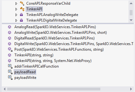
The .Net library I have written is SparkIO.WebServices and it has two classes – TinkerAPI and CoreAPI.  The Tinker API class is what we will be focusing on to write our initial application.  We will see what works well and doesn’t work well trying to drive our Cherokey.  When we finish this, we will write a custom program for the SparkCore to drive our Cherokey and have it expose its own REST Services tailored to driving our robot.  So, on to the .Net Tinker API.  Below is the class view of the of the Tinker portion of the .Net library.

TinkerAPI Class View

The first thing you should notice are that the public methods mirror the functions exposed in the Spark Cloud’s Tinker API Web Services.

  • AnalogRead
  • AnalogWrite
  • DigitalRead
  • DigitalWrite

Let’s start with the constructors.  At a minimum, the constructors need your device ID and authentication token.  You can find these by going to the Spark Build interface and following the steps in the documentation.  The second constructor let’s you supply a WebProxy object to the SparkCore.Net library in the event your network needs one or if you want to route traffic through Fiddler to trouble shoot your REST calls.

The SparkCore.Net library makes use of the HttpWebRequest and HttpWebResponse classes to send and receive data to/from the Spark Cloud REST services.  The responses from the Spark Cloud are JSON so the library uses JsonSerializer along with some Data Contract classes to read the data and make it accessible.  You are welcome to dive into the source code and look at all of the specifics.  This should be enough information to keep you going at this point.  Below is a snippet of code showing the basic use of the TinkerAPI .Net library to initilize the TinkerAPI class and to set pin D0 HIGH, wait 5 seconds and then set pin D0 LOW.

using System;
using System.Text;
using System.Threading;
using System.Threading.Tasks;
using SparkIO.WebServices;

namespace ConsoleApplication1
{
    class Program
    {
        private const string coreID = "yourcoredidhere";
        private const string accessToken = "yourcoreaccesstokenhere";

        static void Main(string[] args)
        {
            TinkerAPI tinker = new TinkerAPI(coreID, accessToken);

            tinker.DigitalWrite(TinkerAPI.Pins.D0, TinkerAPI.SetStates.HIGH);

            Thread.Sleep(2000);

            tinker.DigitalWrite(TinkerAPI.Pins.D0, TinkerAPI.SetStates.LOW);
        }
    }
}

A quick read of the code shows line 16 where we initialize the TinkerAPI object with your Core’s ID and Access Token. You can get this for the online Build page at the SparkCore site.  Line 18 turns pin D0 to a HIGH state and line 22 sets it LOW.  Simple!  So let’s drive a robot!

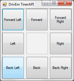
The DrivEm Application is a C# WinForms application that uses the TinkerAPI to drive our robot we assembled above.  The form has a collection of buttons that fire functions in a helper class.  This simple form is shown below.

DrivEm Interface

Let’s take a look at first the initialization of the TinkerAPI and then the button up/down events to move the robot forward and stop it.  This code exists mainly in the Helper class included with the WinForm app.  In the WinForm’s Constructor, we instantiate the Helper class and assign it to a form level variable.

private Helper helper;

public frmMain()
{
    InitializeComponent();
    helper = new Helper();
}

The helper class simply calls the constructor on the TinkerAPI class while passing in the CoreID and the AccessToken.  The TinkerAPI class is one of two classes in the SparkIODotNet library.  The TinkerAPI exposes the TinkerAPI methods in a .Net library.  The other library, CoreAPI, will be shown in part 2 of this article.  It can be used to call the Spark’s web functions and variables that can be made use of in a SparkCore program.

public Helper()
{
    tinker = new TinkerAPI(coreID, accessToken);
}

At this point we are ready to go and start changing pin states to get the robot moving. To accomplish this, we wire up the Forward button’s MouseDown and MouseUp events as follows.

private void btnForward_MouseDown(object sender, MouseEventArgs e)
{
    helper.GiveCommand(Helper.DriveCommands.Forward);
}

private void btnForward_MouseUp(object sender, MouseEventArgs e)
{
    helper.GiveCommand(Helper.DriveCommands.Stop);
}

The helper object has a GiveCommand method that is passed an Enum used to tell the helper what to do. In our case, we see the use of Forward and Stop. The first when the button is depressed and the later when it is released. This gives the functionality where the user has to maintain the press to keep the robot moving forward. Let’s take a look at what goes on in the Helper class when it receives this command.

public void GiveCommand(DriveCommands command)
{
    switch (command)
    {
        case DriveCommands.Forward:
            driveCommand(TinkerAPI.SetStates.HIGH, TinkerAPI.SetStates.HIGH, Speed.speedFull, Speed.speedFull);
            break;
        case DriveCommands.ForwardLeft:
            driveCommand(TinkerAPI.SetStates.HIGH, TinkerAPI.SetStates.HIGH, Speed.speedHalf, Speed.speedFull);
            break;
        case DriveCommands.ForwardRight:
            driveCommand(TinkerAPI.SetStates.HIGH, TinkerAPI.SetStates.HIGH, Speed.speedFull, Speed.speedHalf);
            break;
        case DriveCommands.Left:
            driveCommand(TinkerAPI.SetStates.LOW, TinkerAPI.SetStates.HIGH, Speed.speedFull, Speed.speedFull);
            break;
        case DriveCommands.Right:
            driveCommand(TinkerAPI.SetStates.HIGH, TinkerAPI.SetStates.LOW, Speed.speedFull, Speed.speedFull);
            break;
        case DriveCommands.Rear:
            driveCommand(TinkerAPI.SetStates.LOW, TinkerAPI.SetStates.LOW, Speed.speedFull, Speed.speedFull);
            break;
        case DriveCommands.RearLeft:
            driveCommand(TinkerAPI.SetStates.LOW, TinkerAPI.SetStates.LOW, Speed.speedHalf, Speed.speedFull);
            break;
        case DriveCommands.RearRight:
            driveCommand(TinkerAPI.SetStates.LOW, TinkerAPI.SetStates.LOW, Speed.speedFull, Speed.speedHalf);
            break;
        case DriveCommands.Stop:
            driveCommand(null, null, Speed.speedStop, Speed.speedStop);
            break;
    }
}

The function takes the command and passes it through a case statement which executes the driveCommand function with the proper arguments for the command passed in. In the case of forward, you see that it it sets LeftDir and RightDir to HIGH so that both motors will turn in the forward direction. It then sets LeftSpeed and RightSpeed to the speedFull value which tells the motors to start turning at full speed. Below is the implementation of driveCommand and the calls itmakes to the TinkerAPI to get the robot moving.

private void driveCommand(TinkerAPI.SetStates? LeftDir, TinkerAPI.SetStates? RightDir, Speed LeftSpeed, Speed RightSpeed)
{
    if (LeftDir.HasValue && RightDir.HasValue)
    {
        tinker.DigitalWrite(leftDirPin, LeftDir.Value);
        tinker.DigitalWrite(rightDirPin, RightDir.Value);
    }

    tinker.AnalogWrite(leftMotorPin, (short)LeftSpeed);
    tinker.AnalogWrite(rightMotorPin, (short)RightSpeed);
}

The drive command will set the states of the four pins that drive the robot. Recall that the two digital pins control the direction of the left and right motors while the analog pins control the speed. DriveCommand first looks to see if there are explicit values provided for the left and right motor direction. If not, the motor states are left alone. This is as such for the event that the speed only wants to be altered and the direction pins allowed to stay in their current state. The next thing the DriveCommand does is to set the speed of the motors.

The DriveCommand worked well enough but there was a problem.  When making the calls on lines 9 and 10 to get the robot moving, the network latency was causing the robot to jerk to the right by a few degrees when starting to roll.  This is because we are calling the methods serially and there is a round trip delay between making the call the SparkCore on-board the robot and having it return.  To solve this problem, I had to set up delegates and perform the calls asynchronously.  Although we are still calling the Left and Right speed commands serially, the use of asynchronous calls makes it parallel for our purpose. Take a look at the revised code we use in DriveCommand to accomplish this below.

private void driveCommand(TinkerAPI.SetStates? LeftDir, TinkerAPI.SetStates? RightDir, Speed LeftSpeed, Speed RightSpeed)
{
    TinkerAPI.DigitalWriteDelegate dwdL = new TinkerAPI.DigitalWriteDelegate(tinker.DigitalWrite);
    TinkerAPI.DigitalWriteDelegate dwdR = new TinkerAPI.DigitalWriteDelegate(tinker.DigitalWrite);

    TinkerAPI.AnalogWriteDelegate awdL = new TinkerAPI.AnalogWriteDelegate(tinker.AnalogWrite);
    TinkerAPI.AnalogWriteDelegate awdR = new TinkerAPI.AnalogWriteDelegate(tinker.AnalogWrite);

    IAsyncResult resultL;
    IAsyncResult resultR;

    if (LeftDir.HasValue && RightDir.HasValue)
    {
        resultL = dwdL.BeginInvoke(leftDirPin, LeftDir.Value, null, null);
        resultR = dwdR.BeginInvoke(rightDirPin, RightDir.Value, null, null);

        TinkerAPI.GetStates gsresultL = dwdL.EndInvoke(resultL);
        TinkerAPI.GetStates gsresultR = dwdR.EndInvoke(resultR);
    }

    resultL = awdL.BeginInvoke(leftMotorPin, (short)LeftSpeed, null, null);
    resultR = awdR.BeginInvoke(rightMotorPin, (short)RightSpeed, null, null);

    bool bresultL = awdL.EndInvoke(resultL);
    bool bresultR = awdR.EndInvoke(resultR);
}

The below video shows the results of the code. Watch the robot go for a spin! In part 2 of this article, I will modify this DrivEm application to use custom code I push to the SparkCore to reduce the complexity of the code on the client side.